My box arrived after I paid the Ł37 customs fee. I opened it straight away (as you would). I had taken the day of work to do painting and decorating at home to get the lab/workshop/girlfriend’s study ready, but I guess that will have to wait! How fortuitous! Let’s see how quickly I can get this thing up and running without making any mistakes (and doing this blog thing).
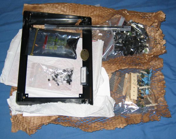
Everything was well packaged and I love the paper net wrapping. My girlfriend has bagged them for making a collage resource (she is a primary school teacher).
Next step. Printed out the parts list from the website so I can check all the bits are present (see I am doing this properly and not just soldering wildly).
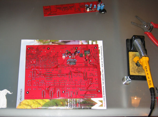
OK so that took a little longer than expected (running out of time!). I think it will be worth the effort and stop any panics later. Firstly I prepared the surface...
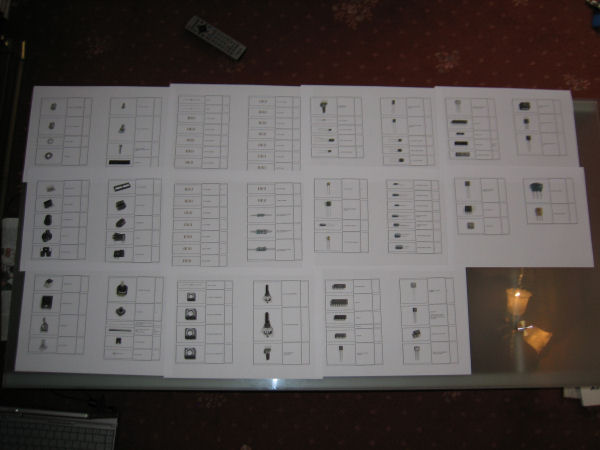
Then I went through the bags reading off the tiny markings and was delighted to find almost all parts were present. The only things missing were one of the 4-40 lock washers (after a quick scramble on the floor, search in the box, definitely look right in the bottom of the plastic bag I had to accept it was missing), and the 2K2 5% resistors :( Here's how it looks (it was worth the time, I keep convincing myself):
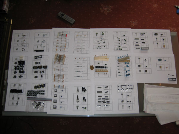
Things are alright because I've looked through my stocks and I have a similar enough washer, and fortunately the required resistors too. So I am happy.
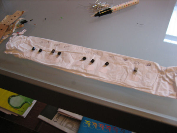
Next step. Have a cup of tea. Then bag up the bits and label so I don't need to sort them out again. "Before everything else, getting ready is the secret to success" - Henry Ford
OK so tea and emailing took half an hour. Bagging up took half an hour. And finally soldering the USB chip took half an hour. Quite pleased with my first attempt at surface mount soldering. It looks OK and I have checked continuities and stuff.
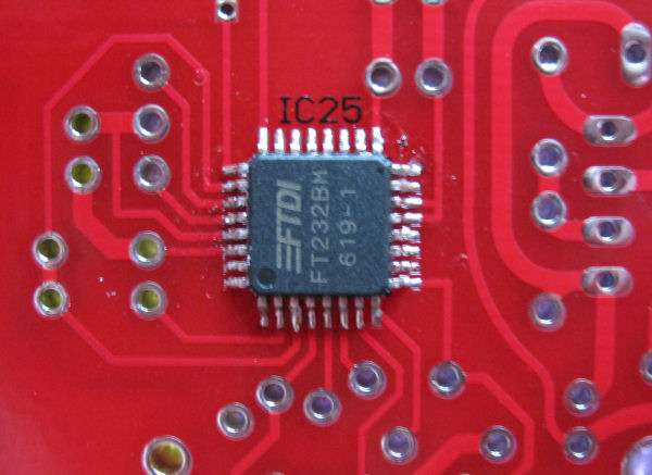
I must agree that solder wick is essential because although you sometimes get a good run on the pins, getting 8 or 9 done perfectly, the shakes tend to kick in and two pins will get bridged by a big shiny blob. Also forgot to mention that instead of the missing parts listed earlier, I did get an extra DIL socket for the CPU and also a bonus allen key, which made me laugh because I didn't get any hex screws, they were all cross-heads
Next step POWER
I'm not going to be finished tonight I reckon. Power done and tested all voltages good. I'm using molex type connectors on my board because that's what I'm used to and find convenient.
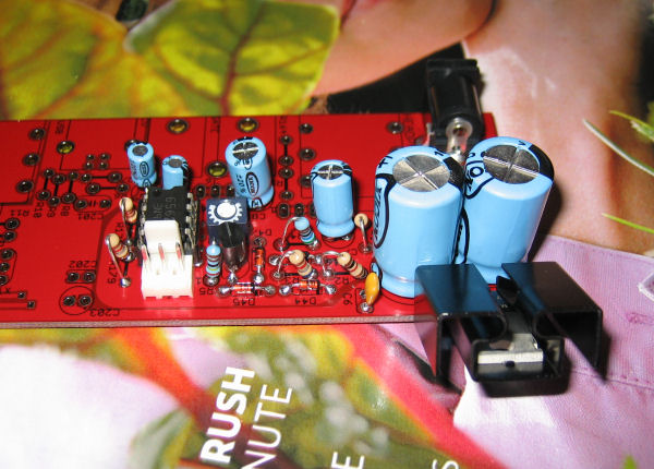
Next step lunch then VCO...
I have built the VCO. I have not calibrated it as I don't have a scope or cheap headphones or a power supply. I will try and do some checking tomorrow, but I really must do a little bit of decorating so I'm not in trouble. I have however taken the time to rate my 2SA733Ps beta values. I also have a reasonable supply of 2SA733Ps of my own and found that they were mostly higher than the supplied ones. I picked a 332 and two 325s to use in Q10,Q9,Q8. I am also socketing these transistors using a chopped up 14-pin DIL socket. As an aside I was hoping to have more of these 733s to pick from but the last 80 I ordered turned out to be 2SA733Ys or something coming in with betas at 160. I guess these will be useless. I am also socketing all ICs.
Next step painting the house. Then maybe connect up VCO, but is it worth it without a scope? Maybe just straight onto VCF...
Well I did a little painting then had to go aout and play pool with some mates. This involved beer so I got up a little late today. But I have completed the VCF. I am skipping all testing and calibrating that uses a scope until complete and I might be able to get one. The VCF was easy to make and uneventful apart from the excitement of socketing Q10 and Q9 with my specially chosen bits. Oh, yeah I also cut the pots down to size.
So I'm ready for breakfast and then the Envelope appears to be next on the list...
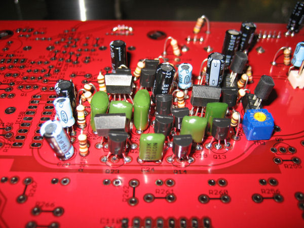
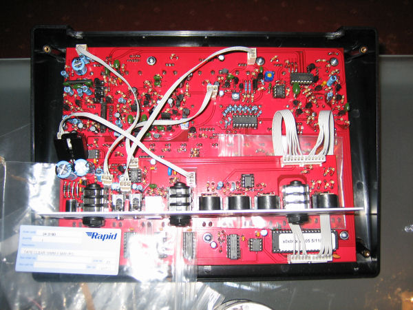
That was a long day. I have made excellent progress considering my missus came home at lunch time so I had to do some work in the bathroom scraping mouldy sealant from around the bath. Anyway, here is the main board now:
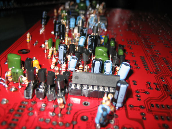
Notice my awsome sockets just in case I swap out the BA6110 for a BA662A in the future. Actually, that photo is not the latest; I have done the headphone section as well.
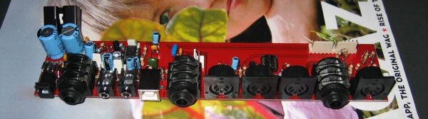
The IO board is complete. Here's a trick for you. I couldn't be bothered to go upstairs to find a 6-pin DIL socket so I pulled out two receptors in an 8-pin one and used that for the 4N37. Genius.
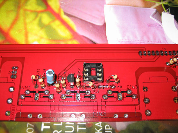
Here is the complete IO board. Again I have used multipole connectors cos I like 'em. I actually labelled them up with their J number after I took the photo as the printing on the board was covered by the sockets and I just know tomorrow I won't have a clue which is which. Also note I was inconsistent in the orientation of the sockets so on some pin 1 is on the left looking down on the socket with the clip on the bottom (if you can imagine), and sometimes on the right. Not a problem as I made sure I mounted the corresponding main board socket the same, but slightly irritating in a perfectionist way...
It's certainly bed time now. I think I am spending some quality time with the bird tomorrow so will have to squeeze in the sequencer part when I can. It is most exciting to be so close to finishing. Just a ton of resistors and IC sockets to cane through...
It's finished!
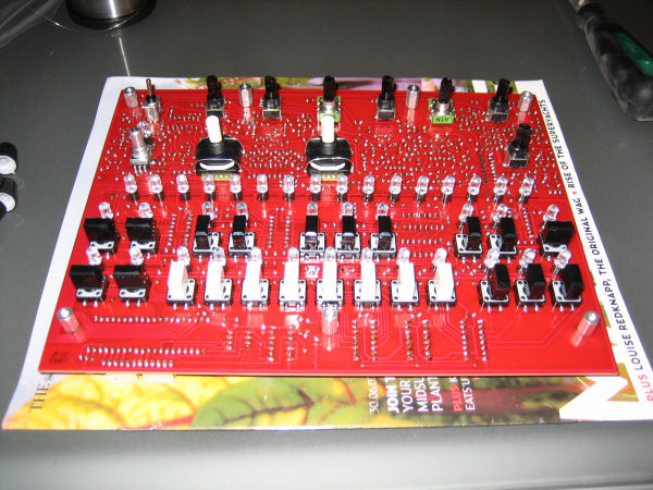
The blog had to take second place to frenetic soldering yesterday as I desperately wanted to finish more and more the closer I got to the end. But to carry on the story first I got the LEDs and switches on:
Getting the LEDs in the correct place was easier than I had expected. I put them all in their standoffs and dropped them into their holes loose. Then fitted the PCB to the front panel in the case upside down allowing them to drop through the holes with a bit of jiggling. Then put solder on one pin of each to hold them steady. Then I held the case on it's side and while heating each soldered pin just pushed them flush, then I could easily finish the soldering. Dunno if the best way but it worked sweet.
Then did the remaining resistors and stuff. I should have done them before the LEDs as it was a little fiddly getting the iron tip between the LEDs without melting them! Never mind. So then I did the switches and keycaps:
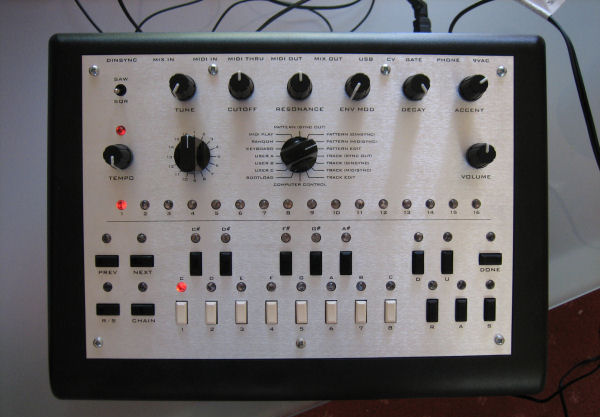
That was everything done except the connecting cables. This was frustrating as they take a while and I just wanted to hear some beeps! But I got it done while watching From Dusk Till Dawn and I was very pleased:
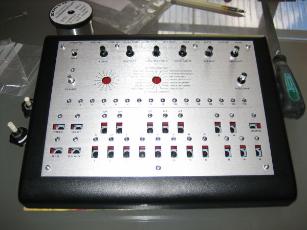
And that was it! Complete! And it worked!!!!!!
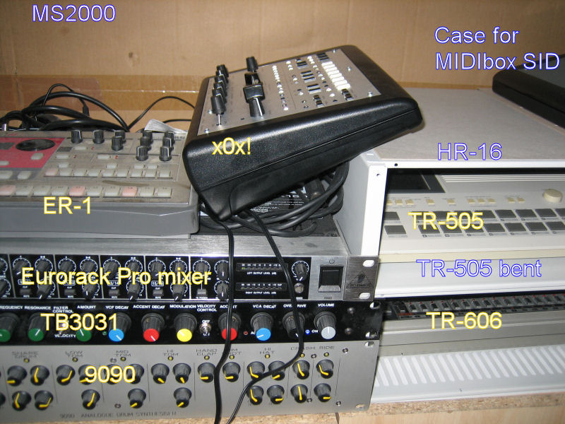
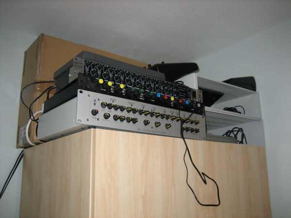
Finally here it is in my studio setup on top of my wardrobe because as you know I haven't decorated the lab due to soldering being more fun! You can see some of my other equipment (some of which is hidden inside the rack cases (which are reserved for future DIY projects) and a big box). I can't wait to get it up and running with my 9090 but I don't have my MIDI set up properly or a decent PC sequencer yet (probably need Ableton...)
And really finally here is a quick sample I made to prove it works and is awesome (and I know how to use the sequence editor and the knobs) and I love it:
x0x.wma